
本文目前僅提供英文版本。
An experienced HVAC estimator does not start a take-off on the first floor plan. She starts on the cover sheet, reads the legend and the general notes, flips to the schedules, and only then begins counting. By the time she counts the first diffuser, she already knows what the engineer's symbols mean, which notes change the scope, and where the set is likely to disagree with itself.
A machine that wants to produce a take-off she can trust has to read the set in the same order and for the same reasons.
What is in a mechanical set
- Cover sheet and legend. Symbols, line types, abbreviations and the engineer's own conventions.
- General notes. Scope boundaries, coordination requirements and the notes that apply everywhere.
- Floor and roof plans. Duct and piping layouts, equipment locations, air devices and their tags.
- Enlarged plans and sections. Mechanical rooms, shafts, congested areas and vertical relationships.
- Details. Typical installation details for equipment, dampers, supports and connections.
- Schedules. Equipment, fans, pumps, terminal units and air devices, with capacities, sizes and models.
- Controls. Sequences of operation and points lists.
- The project manual. Division 23 specifications that govern products, materials, insulation, testing and balancing.
The legend comes first
Mechanical drawings have conventions, but every engineer's set has its own variations. Supply, return and exhaust ducts may be distinguished by line type or by annotation. Air devices are tagged with a type and an airflow. Equipment tags follow patterns such as AHU-1, RTU-2, EF-3 or VAV-3-14, where the middle number may mean a floor. Abbreviations vary from firm to firm.
The legend sheet is where these choices are declared. Reading it first is not a formality. It is the difference between counting a symbol as a fire damper and counting it as a balancing damper.
Counting what is drawn
A take-off is more than a symbol count.
- Equipment. Rooftop units, air handlers, fans, pumps, boilers, chillers and terminal units, each tied to its schedule line.
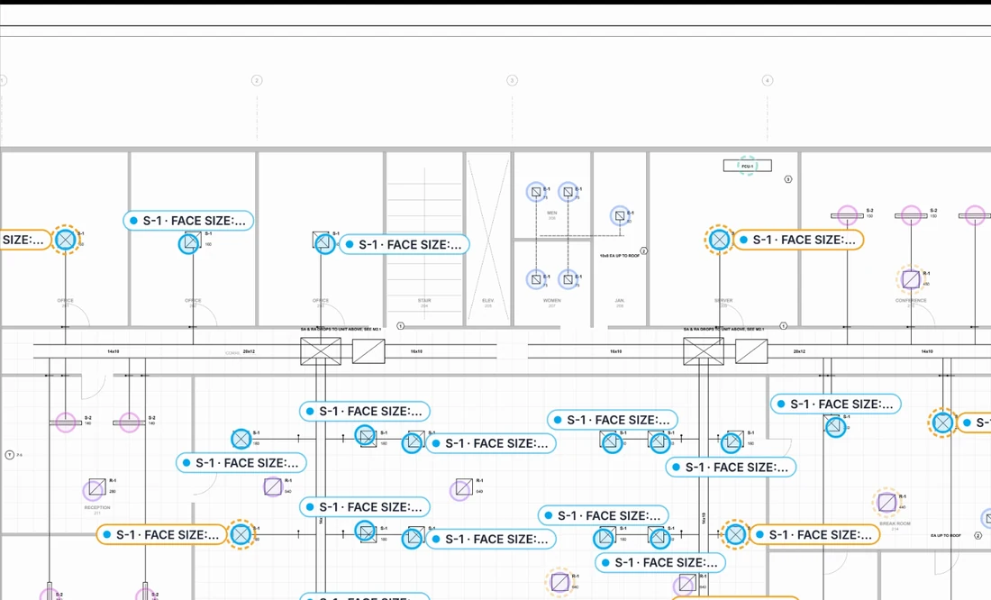
- Air devices. Diffusers, registers and grilles by type and size, usually the longest list in the take-off.
- Dampers. Fire, smoke and combination dampers where ducts cross rated assemblies, and balancing dampers at branches.
- Ductwork. Lengths by size and material, with the fittings that drive labor: elbows, transitions, takeoffs and offsets.
- Piping. Hydronic, refrigerant and condensate, by size and material.
- Insulation and lining. Driven by the specification, not the plans.
Duct is where reading becomes measuring. Sizes are written as text beside the duct, lengths come from the drawing scale, and a run often continues on the next sheet across a match line.
Where counts go wrong
Most take-off errors are not miscounts. They are misreadings of how the set is organized.
- Enlarged plans. A mechanical room drawn at a larger scale also appears on the base floor plan. Count both and the equipment is doubled.
- Typical floors. "Typical for floors 3 to 7" multiplies one plan by five, and a single exception on floor 5 hides in a note.
- Scope notes. "By others", "not in contract" and "existing to remain" remove items that are plainly drawn.
- Alternates. Items priced separately must be counted separately.
- Schedules against plans. A unit scheduled but not drawn, drawn but not scheduled, or tagged differently on each.
- Addenda. A reissued sheet changes some items and not others, and a revision cloud does not always mark them all.
An estimator catches these because she reads the notes and the structure of the set before she counts. A system that only detects symbols cannot.
Why this is hard for a machine
- Dense sheets. Symbols overlap with text, tags and dimension lines, especially in mechanical rooms and ceiling plenums.
- Measurement, not just detection. Double-line duct has to be followed and measured at scale, with sizes read from nearby text.
- Notes with logic. "Typical", "by others" and alternates change counts in ways only the notes describe.
- Connections across sheets. Match lines and continuation notes split runs that have to be joined.
- Tables with structure. Schedules use merged cells, footnotes and abbreviations that change their meaning.
- Scans. Older or printed-and-scanned sets bring skew, noise and faded linework.
How a verified take-off is built
- Read the legend and notes. The set's own symbols, abbreviations and scope rules are captured first.
- Detect and tag. Equipment, devices and duct are found on the plans and their tags read.
- Resolve against schedules. Each tagged item is tied to its schedule line, and mismatches are listed.
- Apply the set's structure. Typical floors, enlarged plans, scope exclusions and alternates are applied, and each application is shown for a person to confirm.
- Measure. Duct and pipe lengths are measured at the drawing scale, by size and material.
- Route doubt. Anything below the confidence threshold goes to the estimator with the sheet region open.
- Export with links. The take-off goes out in the estimating format, and every line opens the region of the sheet behind it.
The estimator's role moves from counting to checking. That is not a smaller role. It is the part of the job that needs her judgment.
What the estimator still decides
Labor units, crew productivity, material pricing, risk, and the interpretation of an ambiguous scope note all stay with the estimator. So does the decision to raise an RFI or carry a number. A good take-off makes those decisions better informed. It does not make them.
Read the set once
Every addendum, every submittal and every change order on the project refers back to the same drawings. A set that has been read and verified once can answer all of them: what changed in the addendum, whether the submitted unit matches the schedule, what a change touches. The bid is the first use of that work, not the last. See HVAC take-off and our page for HVAC and mechanical contractors.